One simple application of the motor effect is the DC electric motor. A simple electric motor consists of a current-carrying loop situated in a magnetic field, with its plane initially parallel to the field direction. Clearly, for the loop to continue to rotate in one direction, the current running through the loop must reverse direction just as the loop reaches the position where it is perpendicular to the field direction. A split ring commutator is used to achieve this reversal of the current direction.
The split ring commutator is attached to the loop and conducts current into the loop by rubbing against the brushes. The brushes are usually carbon rods that carry current from the external power source to the commutator. See the diagram below (note that it has not been drawn to scale – commutator has been drawn larger than is actually the case):
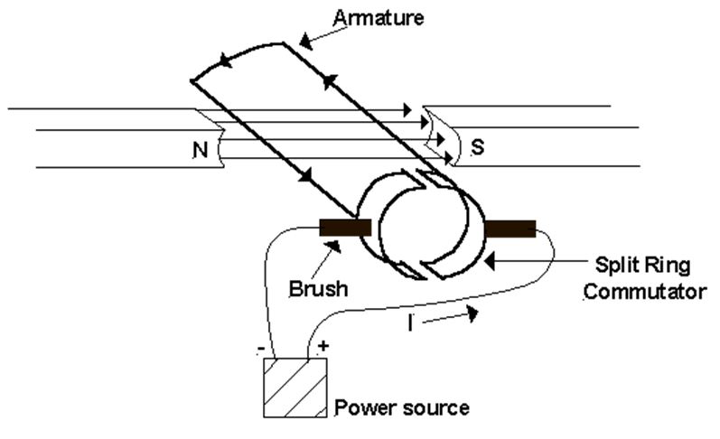
The split ring is arranged so that each half of the commutator changes brushes just as the loop reaches the position where its plane is perpendicular to the field direction. Changing brushes reverses the current in the loop. As a result, the direction of the force on each side of the loop is reversed and the loop continues to rotate in the same direction. This process is repeated each half-turn. Thus, the loop spins in the magnetic field.
In practice, electric motors have several rotating loops. Together they make up the armature (or rotor) of the motor. The magnetic field in which the armature sits is called the field structure (or stator) of the motor. This can be produced either by permanent magnets as in the simple case shown above or more usually by current-carrying coils called field coils wound around iron cores called pole pieces. These sit opposite one another inside the motor frame.
Source : http://webs.mn.catholic.edu.au/physics/emery/hsc_motors.html
