MAGNETIC CONTACTOR (chapter 8)

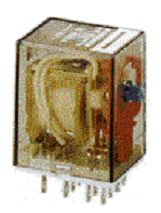
The magnetic contactor is similar in operation to the electromechanical relay (EMR).

The National Electrical Manufacturers Association (NEMA) difines a magnetic contactor as a magnetically actuated device for repeatedly establishing or interupting an electric power circuit.

WP_20140514_001

The electromagnetically operated contactor is one of the most useful mechanisms ever devised for closing and opening electric circuits.

WP_20140514_002

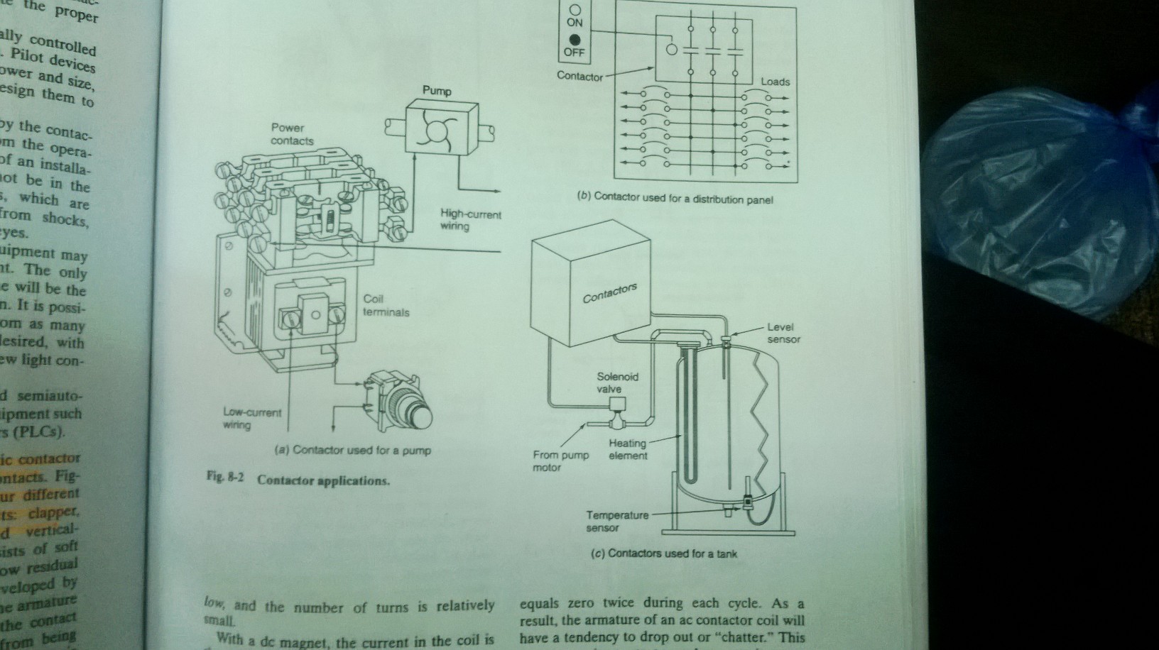
Contactors are used to switch power ON and OFF to a distribution panel.

They are also used with pilot devices to control the temperature and liquid level of a tank.

The advantages of using magnetic contactors instead of manually operated control equipment include the following :

  • Where large currents or high voltages have to be handled, it is difficult to build a suitable manual apparatus. Furthermore, such an apparatusis large and hard to operate. On the other hand, it is a relatively simple matter to build a magnetic contactor that will handle large currents or high voltages, and the manual apparatus must control only the coil of the contactor.
  • Contactors allow multiple operations to be performed from one operator (one location) and interlocked to prevent false and dangerous operations.
  • Where the operation must be repeated many times an hour, a distinct saving in effort will result if contactors are used. The operator simply has to push a button and the contactors will automaically initiate the proper sequence of events.
  • Contactors can be automatically controlled by very sensitive pilot devices. Pilot devices of this nature are limited in power and size, and it would be difficut to design them to handle heavy current directly.
  • High voltage may be handled by the contactor and kept entirely away from the operator, thus increasing the safety of an installation. The operator also will not be in the proximity of high-power arcs, which are always a source of danger from shocks, burns, or perhaps injury the eyes.
  • With contactors the cont rol equipment may be mounted at a remote point. The only space required near the machine will be the space needed for the pushbutton. It is possible to control one contactor from as many different pushbuttons as are desired, with only the necessity of running a few light control wires between the stations.
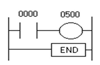
  • Wirth contactors, automatic and semiautomatic control is possible with equipment such as programmable logic controllers (PLCs).

COMPUTER FUNDAMENTALS (chapter 13)

Computer, articularly personal computers, are now accepted as useful devices for machine and process control. As manufacturing systems are becoming increasingly computer-based, understanding of computer fundamentals is essential.

WP_20140513_033

All compputer consist of two basic components: hardware and software. The computer hardware is the physical component which makes up the computer system and includes:

  • Power supply
  • Floppy drives
  • Hard drive
  • Motherboard
  • Microprocessor chip
  • ROM chips
  • RAM chips
  • Peripheral cards
  • Expansion slots

Software is what gives the computer “life”. The software resides inside the hardware. You can think of software as a computer program. A computer program is nothing more than a list of instructions telling the computer what to do. The programs are usually stored on some form of mass storage system, such as a floppy disk, and loaded into the computer’s random access memory (RAM) as required.

There are two major catagories of software: system software and application software. Systems software provides the programs that allow you to interact with you computer-to operate the disk drives, the printer, and the other devices used by the computer.

Application software involves programs written to give the computer a specific aplication, such as a word processor. Application software makes up the majority of the software avaible in the market. In order for application software to work in your computer, the system software must first be loaded into the computer’s memory.

A NUMBER SYSTEM AND CODE (chapter 12)

Knoeledge of number systems other than the decimal numbering system is quite useful when working PLCs or with almost any type of digital equipment. This is true because a basic requirement. This is true because a basic requirement of these divices is to represent, store, and operate on a numbers. In general, PLCs work on binary numbers in one form or another; these are used to represent various codes and quantities. Often the programmer needs to be able to perform conversions between the systems, and to perform math functions within each system.

The decimal system, which is most common to us, has a base of 10. The base of a number system determines the total number of different symbols or digits used by the system. For instance, in the decimal system, 10 unique number or digits-the digits 0 through 9-are used.

WP_20140513_024

A comaparison between four common numbering systems: decimal (base 10), octal (base 8), hexadecimal (base 16), and binary (base 2). Note that all numbering systems start at zero.

The binary numbering system (base 2) is the basis af all digital systems. Two state exits in digital equipment, an ON state, which is representative of one (1), and an OFF condition, which is representative of zero (0). The ON condition in a circuit is approximately equal to supply voltage, and the OFF to zero volts or ground. A third state may exist in some logic circuits to produce tri-state logic. This condition is ahigh-impedence or no-voltage state and is not considered in the binary system.

The octal numbering system, a base 8 system, is often used in microprocessor, commputer, and programmable controller systems because 8 data bits make up a byte of information which can be addressed by the PLC user or programmer. Is some intances, programmable controller manufacturers use the octal system to number wiring terminals, programmable controller racks, and other PLC hardware. The octal number system makes use of 8 digits: 0 through 7. As in all other number systems, each digit in an octal number has a weighted decimal value according to its position.

WP_20140513_030

The hexadecimal (hex) number system provides even shorter notation than octal. Hexadecimal uses a base of 16. It employs 16 digits, numbers 0 through 15, respectively. The techniques for converting hexadecimal to decimal and decimal to hexadecimal are the same as those used for binary and octal.

WP_20140513_031

The binary coded decimal (BCD) system provides a convenient means to handle large numbers that need to be input to or output from a PLC. The BCD system represents decimal numbers as patterns of 1s and 0s. This system provides a means of converting a code readily handled by humans (decimal) to a code readily handled by the equipment (binary).

TYPES OF PROCESSES (chapter 11)

The types of processes carried out in modern manufacturing industries can be grouped into three general areas, in terms of the kind of operation that takes place, as:

  • Continous process
  • Batch production
  • Individual products production

A continous process is one in which raw materials enter one end of the system and the finished product comes out the other end of the system: the process itself runs continously. Once the process commences, it is continous for a relatively long period of time. The time period may be measured in minutes, days, or even months, depending upon the process.

WP_20140513_020

Engine blocks are fed into one end of the system and complete engines exit at the other end. In continous type process, the product material is subjected to different treatments as it flows through the pprocess (in case assembly, adjusment, and inspection). Auto assembly involves the use automated machines or robots. At each station, parts are suplied as needed.

In batch processing there is no flow of product material from one section of the process to another. Instead, a set amount of each of the inputs to the process is received in a batch, and then some operation is performed on the batch to produce a finished product is stored, and another batch of product is produced. Each batch of product may be different.

Many chemically based products are manufactured by using batch processes.

WP_20140513_021

Two ingredients are added together, mixed, heated, a third ingredient is added, processed and stored. Each batch made may have differing characteristics by design.

WP_20140513_023

The individual product production process is the most common of all processing systems. With this manufacturing process, a seies of operations produces a useful output product. The item being produced may be required to be bent, drilled, welded, and so on, at different steps in the process. The workpiece is normally a discrete part that must be handled on an individual basis.

COUNT CONTROL (chapter 10)

Counters are devices that will receive a string of count pulses from a machine operation and perform an output function based on a number of counts predetermined by the user. Most counters, like timers, can have internal and delay operation. Interval operations means that a load will be actuated at the end of the counting cycle. Solid-state and electromechanical versions are avaible.

Counters are generally thought of as devices that tabulate or count “things” such as a bottles, cans, boxes, castings, and so on. In many industrial control sytems, it is necessary to counts something that affects a controlled process. When the count reaches a certain number, a control action is initiated.

WP_20140513_018

In a mechanical counter, every time the actuating lever is moved over, the counter adds one number, and the actuating lever returns automatically to its original positions. Resetting to zero is done by a pushbutton located on the side of the unit. In an electronical counter, the count set point can be adjusted by the knob on the front of the unit. A progess pointer, indicating the count progession, advances clockwise, from setpoint to zero. A solid-state counter has high-speed pulse operation with 100% accurancy and has programmable features. Counter ouput action occurs when the count total indicated by the thumbwheel switches is reached.

ALTERNATING CURRENT MOTORS (chapter 6)

An ac motor is particularly well suited for constant-speed applications. This is because its speed is determined by the frequency of the ac voltage applied to the motor terminals.
The dc motor is better suited than an ac motor for some uses, such as those that require variablespeeds.
An ac motor can also be made with variable speed characteristics but only within certain limits.
Industry builds ac motors in different sizes, shapes, and ratings for many different types of jobs.
These motors are designed for use with either polyphase or single-phase power systems. It is not possible here to cover all aspects of the subject of ac motors. Only the principles of the most commonly used types are dealt with in this chapter.
Ac motors will be divided into (1) series, (2) synchronous, and (3) induction motors.
Single-phase and polyphase motors will be discussed. Synchronous motors, may be considered as polyphase motors, of constant speed, whose rotors are energized with dc voltage.
Induction motors, single-phase or polyphase, whose rotors are energized by induction, are the most commonly used ac motor. The series ac motor, in a sense, is a familiar type of motor.

What are the three basic types of ac motors?

chap66
SERIES AC MOTOR
A series ac motor is the same electrically as a dc series motor. Refer to figure 4-1 and use the lefthand rule for the polarity of coils. You can see that the instantaneous magnetic polarities of the armature and field oppose each other, and motor action results. Now, reverse the current by reversing the polarity of the input. Note that the field magnetic polarity still opposes the armature magnetic polarity. This is because the reversal effects both the armature and the field. The ac input causes these reversals to take
place continuously.

ROTATING MAGNETIC FIELDS
The principle of rotating magnetic fields is the key to the operation of most ac motors. Both synchronous and induction types of motors rely on rotating magnetic fields in their stators to cause their rotors to turn.
The idea is simple. A magnetic field in a stator can be made to rotate electrically, around and around.
Another magnetic field in the rotor can be made to chase it by being attracted and repelled by the stator field. Because the rotor is free to turn, it follows the rotating magnetic field in the stator. Let’s see how it is done.
Rotating magnetic fields may be set up in two-phase or three-phase machines. To establish a rotating magnetic field in a motor stator, the number of pole pairs must be the same as (or a multiple of) the number of phases in the applied voltage. The poles must then be displaced from each other by an angle equal to the phase angle between the individual phases of the applied voltage.

Relay Ladder Diagram (chapter 7)

2.1         Understanding Relay Ladder Diagram (RLL)

To understand the programming of PLC relay ladder diagram, let us start with simple case of relay control system. We can think of a relay as an electromagnetic switch. Apply a voltage to the coil results in a magnetic field is generated. This magnetic field sucks the contacts of the relay in, causing them to make a connection. These contacts can be considered to be a switch. They allow current to flow between 2 points thereby closing the circuit.

chap7

Fig. 2.5 Simple control circuit of a bell

Let’s consider the following example. Here we simply turn on a bell whenever a switch is closed, as shown in Fig. 2.5. We have 3 real-world parts; A switch, a relay and a bell. Whenever the switch closes we apply a current to the bell causing it to sound. The bottom circuit indicates the DC control circuit. The top circuit indicates the AC control circuit. Here we are using a DC relay to control an AC circuit. That’s the benefit of using relay. When the switch is open no current can flow through the coil of the relay. As soon as the switch is closed, however, current runs through the coil cause a magnetic field to build up. This magnetic field causes the contacts of the relay to close. Now AC current flows through the bell and we hear it. Fig. 2.6 shows a typical industrial relay.

chapt7

Fig. 2.6 A typical industrial relay.

Next, we would like to replace the relay control system with PLC control system using relay ladder logic. After seeing a few of these it will become obvious why its called a ladder diagram. We have to create one of these because, unfortunately, a PLC doesn’t understand a schematic diagram. It only recognizes code. Fortunately most PLCs have software, which convert ladder diagrams into code. This shields us from actually learning the PLC’s code.

The PLC doesn’t understand terms like switch, relay, bell, etc. It prefers input, output, coil, contact, etc. It doesn’t care what the actual input or output device actually is. It only cares that its an input or an output.

First we replace the battery with a symbol. This symbol is common to all ladder diagrams. We draw what are called bus bars. These simply look like two vertical bars. One on each side of the diagram. Think of the left one as being + voltage and the right one as being ground. Further think of the current (logic) flow as being from left to right. Next we give the inputs a symbol. In this basic example we have one real world input. (i.e. the switch) We

1
Fig. 2.7 Contact relay symbol

give the input that the switch will be connected to, the symbol shown below. Fig. 2.7 shows the symbol for contact of switch or relay.

Next we give the outputs a symbol. In this example we use one output (i.e. the bell). We give the output that the bell will be physically connected to the symbol shown below. Fig. 2.8 shows the symbol used as the output coil or relay.

2
Fig. 2.8 Output relay symbol

The AC supply is an external supply so we don’t put it in our ladder. The PLC only cares about which output it turns on and not what’s physically connected to it.

Second, we must tell the PLC where everything is located. In other words we have to give all the devices an address. Where is the switch going to be physically connected to the PLC ? How about the bell? We start with a blank road map in the PLCs town and give each item an address. Could you find your friends if you didn’t know their address? You know they live in the same town but which house? The PLC town has a lot of houses (inputs and outputs) but we have to figure out who lives where (what device is connected where). We’ll get further into the addressing scheme later. The PLC manufacturers each do it a different way! For now let’s say that our input will be called “0000”. The output will be called “500”, as shown in Fig. 2.9.

Finally, we have to convert the schematic into a logical sequence of events. This is much easier than it sounds. The program we’re going to write tells the PLC what to do when certain events take place. In our example we have to tell the PLC what to do when the operator turns on the switch. Obviously we want the bell to sound but the PLC doesn’t know that.

3

Fig. 2.9 RLL for bell control circuit

The Fig. 2.9 shows the final converted diagram (RLL) for bell control system. Notice that we eliminated the real world relay from needing a symbol.


Source : faculty.ksu.edu.sa/…/Chapter2_ver3.doc

The DC Electric Motor (chapter 9)

One simple application of the motor effect is the DC electric motor.  A simple electric motor consists of a current-carrying loop situated in a magnetic field, with its plane initially parallel to the field direction.  Clearly, for the loop to continue to rotate in one direction, the current running through the loop must reverse direction just as the loop reaches the position where it is perpendicular to the field direction.  A split ring commutator is used to achieve this reversal of the current direction.

The split ring commutator is attached to the loop and conducts current into the loop by rubbing against the brushes.  The brushes are usually carbon rods that carry current from the external power source to the commutator.  See the diagram below (note that it has not been drawn to scale – commutator has been drawn larger than is actually the case):

chap6

The split ring is arranged so that each half of the commutator changes brushes just as the loop reaches the position where its plane is perpendicular to the field direction.  Changing brushes reverses the current in the loop.  As a result, the direction of the force on each side of the loop is reversed and the loop continues to rotate in the same direction.  This process is repeated each half-turn.  Thus, the loop spins in the magnetic field.

In practice, electric motors have several rotating loops.  Together they make up the armature (or rotor) of the motor.  The magnetic field in which the armature sits is called the field structure (or stator) of the motor.  This can be produced either by permanent magnets as in the simple case shown above or more usually by current-carrying coils called field coils wound around iron cores called pole pieces.  These sit opposite one another inside the motor frame.

Source : http://webs.mn.catholic.edu.au/physics/emery/hsc_motors.html

PHOTOTRANSISTOR (chapter 5)

chap5

A phototransistor is a special transistor that is sensitive to light.  We can see the actual transistor semiconductor by looking through the window that admits the light.  The square gray block in the center of the device is the actual active part of the transistor – less than 1 mm across.  The picture below (also taken by Anesh Prasai) shows the total phototransistor beside a pencil to indicate te size.  As can be seen the active part of the transistor is the size of the dull pencil point. To make the close-up photo at left Anesh supported a small hi power magnifier in front of the camera lens in order to obtailn a magnified image of the transistor.

chapt5

A transistor consists of three parts: the emitter, base, and collector.  In the photo transistor the emitter is the small circular part near the center of the square with a gold wire leading to it.  The base consists of most of the square with the wire leading to it from the bottom of the device.  The collector surrounds the other two parts of the transistor (underneath the visible square).  The case of the package is connected to the collector.  Light of the proper wavelength striking the base of the transistor “creates” electrons and holes in the base which in turn makes the transistor act as a switch.  The light striking the base “turns on” the switch, thus creating an electrical connection between the other two terminals.  The utility of a phototransistor is to make a switch with no mechanical moving parts.  If the light beam is blocked the circuitry connected to the transistor can turn on-or off a light, open an automatic door, work a TV remote, sense a computer mouse position, or can  be used for timing physics experiments.  This phototransistor is sensitive to infrared light instead of visible light.  This allows the transistor to be used in the presence of ambient light.  When a remote control is used to control a home TV, the remote unit contains an infrared emitting light emitting diode (LED) which flashes a code sequence so that the matching transistor in the TV receiver can receive the code and change the channel for the channel-surfing viewer from the comfort of the couch.

Source : http://www.warren-wilson.edu/~dcollins/PhysPhotOfWeek/20061208PhotoTransistor/

LIGHT SENSORS (chapter 4)

The photovoltaic, or solar cell, is a common light-sensor device that converts light energy directly into electric energy.

WP_20140513_017

Modern silicon solar cells are basically PN junctions with a transparent P-layer. Shining light on the transparent P-layer causes a movement of electrons between P and N-sections, thus producing a small dc voltage. Typical output volage is about 0.5 V per cell in full sunlight.

The photoconductive cell (also called photoresistive cell) is another popular type of light transducer.

Light energy falling on a photoconductive cell will cause a change in the resistance of the cell. One of the more popular types is the cadmium sulfide photocell. When the surface of this device is dark, the resistance of the device is high. When brihtly lit, its resistance drops to a very low value.

There are two main types of photoelectric sensors that are used to sense position. Each emits a light beam (visible, infrared, or laser) from its light emitting element.

A reflective-type photoelectric sensor is used to detect the light beam reflected from the target. A trough-beam photoelectric sensor is used to measure the change in light quantity caused by the target’s crossing the optical axis.

Features of this type of sensor include :

  • Noncontact detection
  • Detection of targets of virtually any material
  • Long detecting distance
  • High response speed
  • Color discrimination
  • Highly accurate detection